
Improvement of ICRF Antenna Performance with Impedance Transformers
The Large Helical Device (LHD) is equipped with two types of antennas for Ion Cyclotron Range of Frequencies (ICRF) heating. One is the high-power-oriented antenna called the FAIT antenna, and the other is called the HAS antenna, where the wavenumber parallel to the magnetic field lines can be controlled. The performance of these antennas has been drastically improved by utilizing two types of impedance transformers.
One method of heating plasma to high temperatures is Ion Cyclotron Range of Frequencies (ICRF) heating. Normally, ICRF heating uses electromagnetic waves with the frequency of several tens of MHz to heat the ions and electrons in the plasma. The Large Helical Device (LHD) is equipped with two types of antennas (devices that transmit electromagnetic waves to the plasma) for ICRF heating. One is called the FAIT antenna, and the other the HAS antenna.
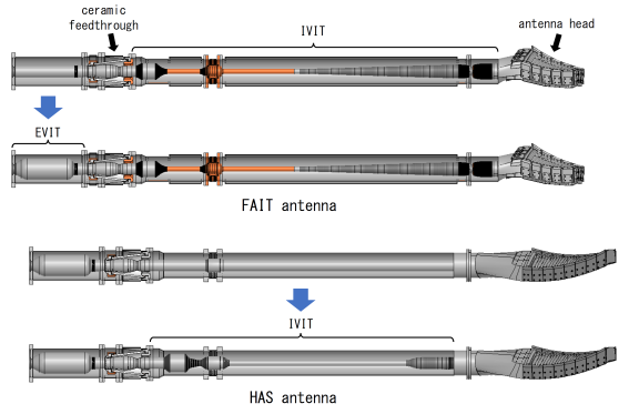
The FAIT antenna is an ICRF antenna optimized for high-power operation. Specifically, by making the head smaller, the voltage applied to the antenna head is reduced even in a high-power operation. Furthermore, an In-Vessel Impedance Transformer (IVIT) is used to suppress the current and voltage around the ceramic feedthrough, which is an important component to maintain a vacuum in the LHD. The IVIT also has an ability to suppress upstream voltage on the transmission line. As shown in the figure, in this modification, an Ex-Vessel Impedance Transformer (EVIT) was also installed just before the ceramic feedthrough, to achieve even higher output power. The loading resistance, which is the value of the transmission power normalized by the square of the transmission line voltage, is used to evaluate the antenna performance. The result of the injection experiments in the LHD showed that the loading resistance increased by a factor of 2.5, which is equivalent to the simulation, and thus the injection of up to 2 MW per one FAIT antenna was enabled in a short-pulse operation.
The HAS antenna is an ICRF antenna that can control the wavenumber in the direction along magnetic field lines. However, loading resistance was originally very low and was not suitable for a high-power operation. Therefore, in 2014 we doubled the loading resistance by installing an EVIT. Protection of the ceramic feedthrough was also an important issue, since the ceramic in the feedthrough (the cone-shaped part in the figure) cracked during an operation in 2010, breaking the vacuum. This kind of problem cannot be solved by the EVIT. Therefore, we modified the transmission line between the ceramic feedthrough and the antenna head to form an IVIT, as in the FAIT antenna. It was confirmed that the loading resistance increased approximately by a factor of four in the experiment of injection into the plasma. This is in close agreement with the simulation results, and we believe that the 60% reduction in power loss between the EVIT and the antenna head and the 50% reduction in current and voltage at the ceramic feedthrough, in case of constant power, have also been achieved as a prediction from the simulation. With this improvement, the HAS antennas have achieved an injection power of 1 MW per one antenna for short-pulse injection.
This research was carried out by a research group of Kenji Saito, Tetsuo Seki, Hiroshi Kasahara and others in the National Institute for Fusion Science. The research results were published on March 18, 2022 in Plasma and Fusion Research, an online journal by the Japan Society of Plasma Science and Nuclear Fusion Research.